Deutsch
 English


Multi Knife Cutter
Overview
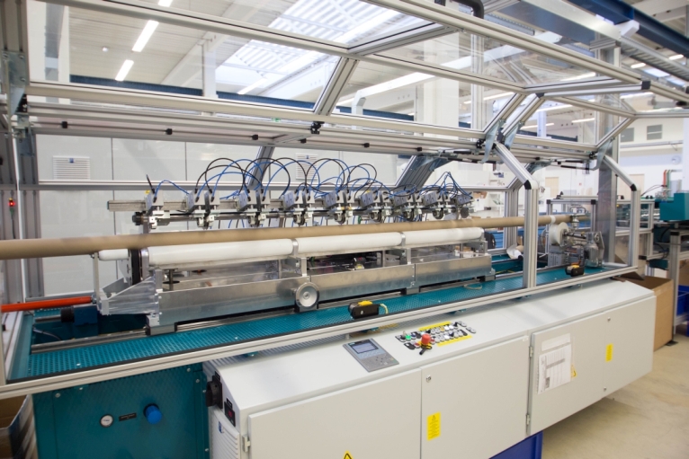
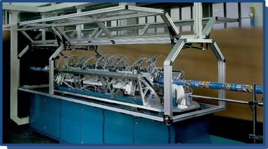
An endlessly spiral-wound and labelled tube is fed to the multi knife cutter from the spiral winder. Winding machine and cutting unit are directly mechanically linked.
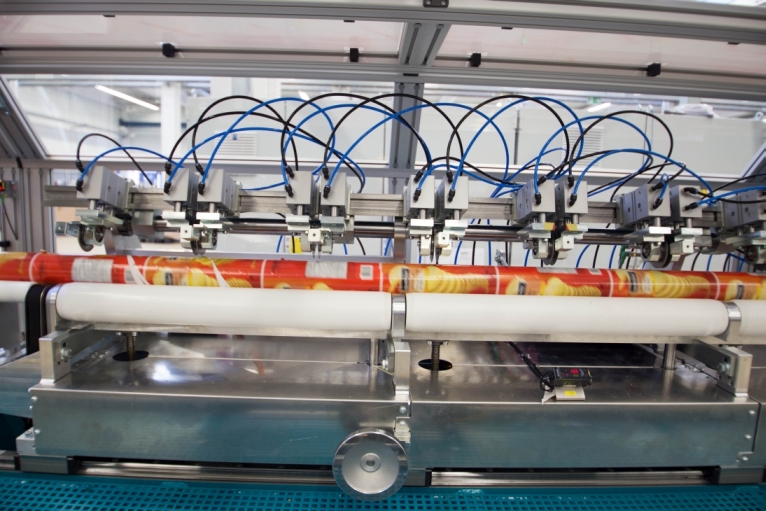
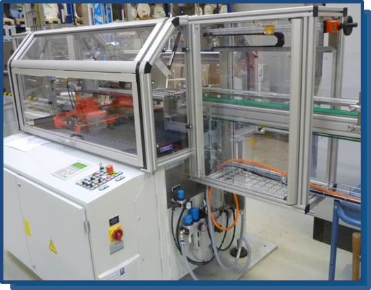
Using a multi knife bar, the tube is cut to the finished length for the can body in accordance with the print image. These bodies are then automatically fed to a combination machine or a seaming / sealing machine.
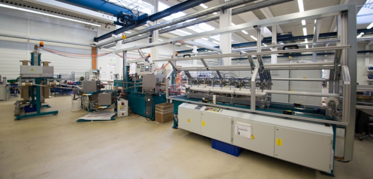
Layout
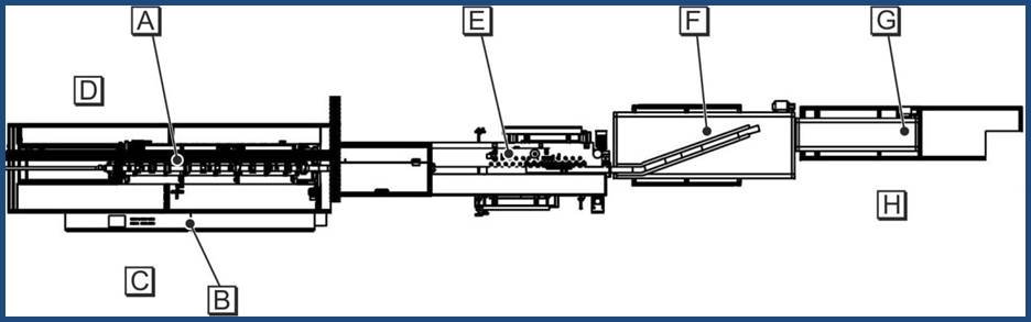
A – cutter
B – cutter control cabinet
C – workstation at the control panel of the control cabinet
D – workstation for setup mode
E – waste ring removal
F – ejector
G – can body upender
H – workplace at the can body upender
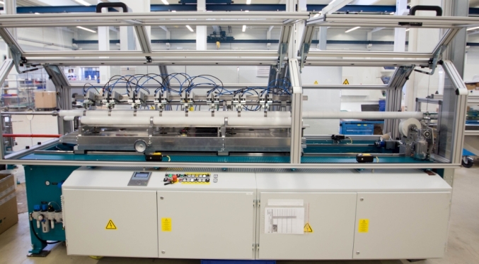
Design and Function
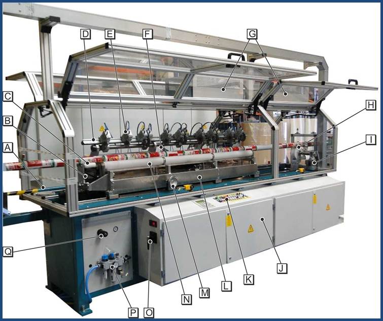
A – connecting rod to the spiral winder
B – support roller drive
C – intake rollers
D – cutter block
E – cutter carrier with crush cutter
F – print mark sensor
G – brake resistor
H – take-off roller
I – take-off roller drive
J – control cabinet
K – EMERGENCY STOP button on the control panel
L – cutter carriage
M – hand wheel for adjusting the height of the support rollers
N – support rollers
O – master switch
P – compressed air maintenance unit
Technical Data
| MULTI KNIFE CUTTER QS7 | |
|---|---|
| performance | max. 120 m / min. |
| tube diameter | Ø 60 ... 120 mm |
| tube wall thickness | max. 1.2 mm |
| section length to be divided | max. 2,100 mm |
| cutting mandrel - center height | 1,250 mm |
| connected load (drives) | 38 kW |
| mass | 2,300 kg (cutter) 450 kg (waste ring removal) 150 kg (ejector) 400 kg (upender) |
| air consumption | approx. 600 l / min. (at 6 bar) |
| pneumatic connection | 6 bar (input pressure) |
Produkte